
FreeCAD Cheatsheet
Installation
Ubuntu PPA:
-
sudo add-apt-repository ppa:freecad-maintainers/freecad-stable
-
sudo apt install freecad
Tuturials
Intro Series: https://m.youtube.com/watch?v=m49z0weonog
Casing: https://m.youtube.com/watch?v=JhPxrHwLFuc
Casing, also using programmatically openSCAD: https://m.youtube.com/watch?v=JhPxrHwLFuc
Recommended introduction: https://www.youtube.com/watch?v=gbNg3mzm84s&list=PL7eiW2bt21YU6QEbly78kUgQCNEiDUwSH
Draft Bench
https://m.youtube.com/watch?v=1iZNhJrm6lk
https://m.youtube.com/watch?v=-ivzKZm_W7g
https://m.youtube.com/watch?v=kmXnDcIqyjY
Search
- View menu -> Views ->Selection view
Deutsch: Ansicht -> Paneele -> Auswahlansicht
Brainfucksafe
Generally use the simple options of the part workbench.
Transformations
Rotate around more than one axis:
- Edit -> Placement
- Checkbox "incremental steps"
Scale, also non-uniformly (squash)
- Draft Workbench
- Clone
- "Scale"
- Hide original object
Sketching
- Sketcher -> Create Sketch
- Fully constrain sketch!
- Fully close lines for rotation objects
- Reference other constraints with formular: Sketch001.Constraints.myradius
Revolve
- Use Part workbench
- Solution for solid 180 revolving?
- Workaround: Part Workbench -> Part -> Create Solid
Pad
- Use Part-Design workbench
Text
- -> Draft
- Select working plane, e.g. xy
- Text to form
- Font directories (Ubuntu)
- /usr/share/fonts
- ~/.local/share/fonts
- Examples:
- 16.04: /usr/share/fonts/truetype/ubuntu-font-family/Ubuntu-B.ttf
- 18.04: /usr/share/fonts/truetype/ubuntu/Ubuntu-B.ttf
- Good Fonts
- Simplo
- /home/klemens/.fonts/Simplo-Black.otf
- Source Sans Pro
- Very bold: https://fonts.google.com/download?family=Source%20Sans%20Pro
- /home/klemens/.fonts/SourceSans3-VariableFont_wght.ttf
- Stencil
- https://fonts.google.com/specimen/Allerta+Stencil
- /home/klemens/.fonts/AllertaStencil-Regular.ttf
- /home/klemens/.fonts/FLAMANTE-STEN.ttf
- Pixel
- /home/klemens/.fonts/PIXY.ttf
- Simplo
- Pad
Global variables
No direct support. Workaround:
- Spreadsheet Workbench
- Create new spreadsheet
- Enter value in a cell
- Right click cell
- Alias: e.g. "wallwidth"
Now you can reference the variable anywhere via "Spreadsheet.wallwidth"
Expressions / Variables
Use reference in sketch:
- Name a constraint, eg. "width"
- Reference it in an other constraint with "Sketch.Constraints.width"
where "Sketch" is the name of the sketch - Placement:
- <<mycube>>.Placement.Base.y
- Shape (e.g. for Clones)
- Shape.BoundBox.XLength
freecad wedge explained
https://www.freecadweb.org/wiki/Part_Wedge/de
The parallel faces are orientated perpenticular to the Y direction.
Wedge Settings as Cube
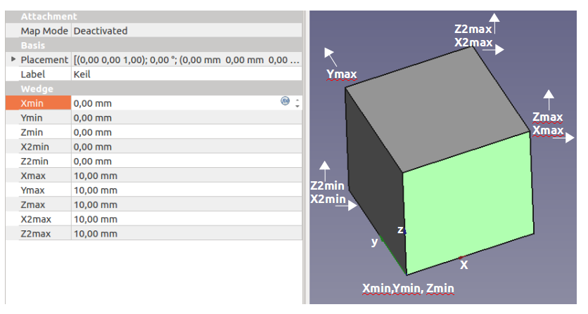
- Xmin, Ymin, Zmin are the coordinates of the point in the axis cross
- Xmax, Zmax are the coordinates of the top right point in the XZ plane
- Ymax is the "height" in the Y axis
- For a cube
- X2min and Y2min need to be the same as Xmin and Ymin (0mm)
- X2max and Y2max need to be the same as Xmax and Ymax (10mm)
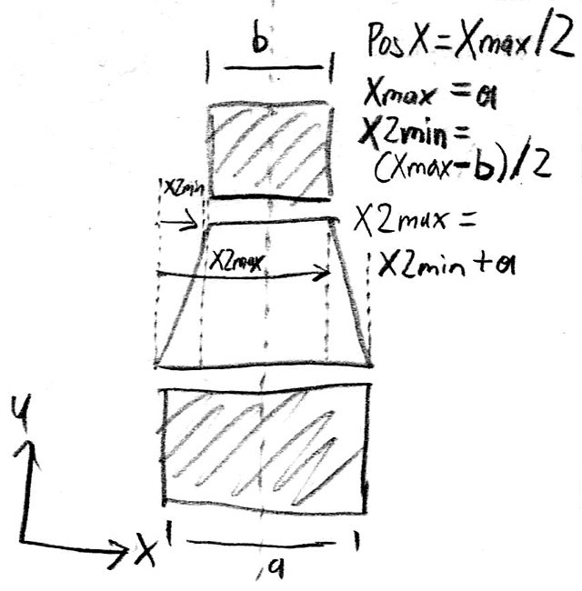
Earlier Wedge Sketch
stl mesh to solid
- Import stl
- -> Part
- Form -> create shape from mesh
Select object, export as .stepDelete or hide objectImport .step- Form -> create solid
Sketch from Image/Photo
- Note the image dimensions and DPI (e.g., 1872x2595 pixels at 300 DPI)
- FreeCad -> File -> Import
- Calculate correct dimensions:
- Width (mm) = (pixel width / DPI) * 25.4
- Height (mm) = (pixel height / DPI) * 25.4
Old:
- Get image aspect ratio, e.g 4608x2592px:4608 / 2592 = 1,78
- Image Workbench -> Icon "Create planar Image in 3D space"
- Use formula for YSize with aspect ratio:
- =XSize / 1,78
- Scale and move to the desired position
- Sketch Workbench -> Create sketch
A spoon with B-spline surface
Installation
- Download latest FreeCad appimg from https://www.freecadweb.org/wiki/Download/en
- Or Download latest dev version for Ubuntu: https://github.com/FreeCAD/FreeCAD/releases/tag/0.19_pre
Add Assembly2 Mod
- https://github.com/hamish2014/FreeCAD_assembly2
- Use manual method
- https://www.youtube.com/watch?v=cT2u1K3X17Q
Settings
- Edit -> Settings
- Language: English
- Startup bench: Part